One-shot calibration for a robot that unscrews cars
A mobile robot drives under a car, finds the screws and unscrews them. The camera-to-tool-tip transform comes from one designed part and one shot, and the whole chain stays under a millimetre.
For an OEM, a mobile robot drives underneath a car. A camera on the arm’s wrist finds the screws in the underbody, and a screwdriver on the arm takes them out. I owned the vision: screw detection and the calibration from camera to tool tip.
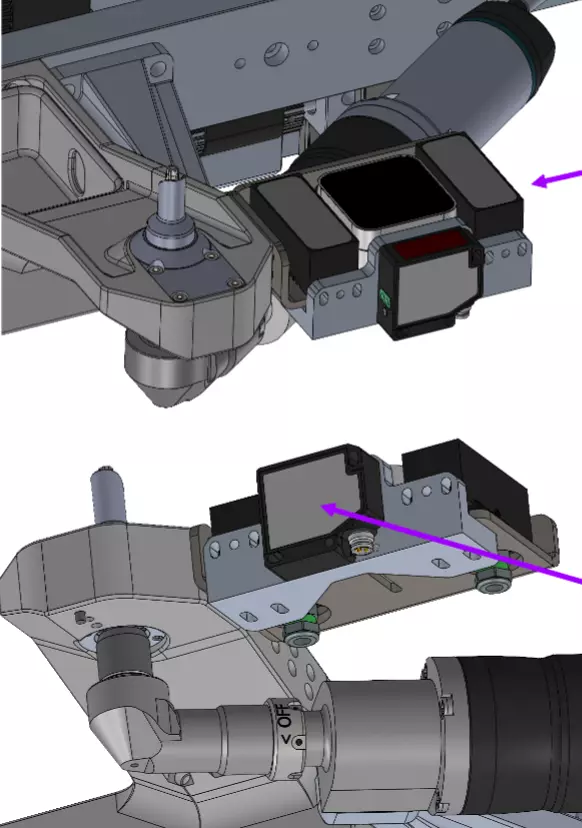
The overall error, from detecting a screw to the tool tip arriving on it, is under a millimetre. How I got that number is at the end.
Finding the screws
Screw detection runs on YOLOv8, on images from a RealSense D405 on the wrist.
Calibration by design
Detecting a screw only helps if you know where it is relative to the tool tip. The usual answer is hand-eye calibration: move the robot through many poses and solve. I designed the problem away instead.
- 1Design the part
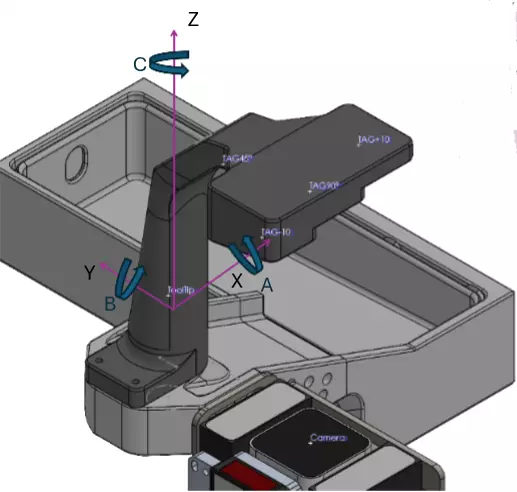
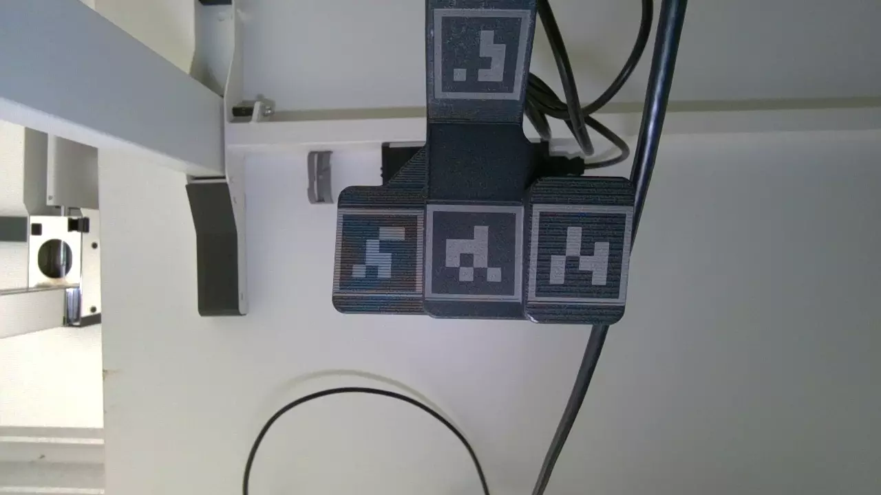
A 3D-printed part on the tool with predefined marker positions. The AprilTags are laser-written onto it.
- 2Know the geometry
From the design, the transform from the tool tip to the tag centre is known exactly.
- 3See the tag
The camera detects the tag and solves its pose with PnP.
- 4Chain them
Camera to tag, tag to tool tip: one shot gives camera to tool tip.
Small things that make it trustworthy
- Flip guard. A single planar tag has a mirror-image pose solution. Step 10 mm along the tag’s normal; if that point gets closer to the camera, the pose is flipped and the frame is rejected.
- Good intrinsics first. The D405 is calibrated on a ChArUco board to 0.14 px RMS.
- Average a few shots. Over 19 captures, the per-frame estimate scattered by at most 0.61 mm in translation and 0.5° in rotation, so averaging only removes detection noise.
- Look before moving. Two 3D viewers draw the camera, tag and tool tip frames. A wrong frame convention, the most common bug in this work, shows up on screen before the robot moves.
The error budget
There is no single ground-truth touch-off, so I measured each link in the chain and added them up.
- 1Screw detection
Shift of the YOLOv8 box centre, measured in pixels and converted to millimetres at the known working distance.
- 2Camera intrinsics
The calibration’s pixel error, converted to millimetres the same way.
- 3Camera to tool tip
The calibration error, which comes down to how precisely the AprilTag centre is detected.
- 4Arm motion
The manipulator’s servo error, measured against the manufacturer’s published figure.
Together they stay under a millimetre, from the pixel to the tool tip.